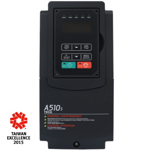

TECO AC Motor Drive A510s Enhanced – Advanced Current Vector Control Drive
Perfect design for heavy overload applications like crane, lift, elevator, drill, punching and pressing machine, with our up-to-date Auto-tuning function, user can reduce mass setup time and fully extends the performance to its limit. Integrate both induction and permanent-magnet motor control technology.
Model (IP20/NEMA1)
200-240V; 1-150HP
380-480V; 1-425HP
500-600V; 1-10HP (2013/3)
Main Features
0-1200Hz output (V/F mode)
Current Vector Control
Speed Control Ratio & Starting Torque
– Close loop: 1:1000, 200%/0Hz
– Open loop: 1:100, 200%/0.5Hz
Speed and Torque Control Mode
PG Option Card
Over Voltage Suppression
PM Motor Control
Download Catalogue and Manual:
TECO Inverter A510s Enhanced Ctlg.pdf
TECO Inverter A510s Enhanced Manual.pdf
Download Software:
JN5 DriveLink setup (V1.73) – 510 series PC-Link